Guest Author

1C1OOCC
I do engineering design for machines and electronics but do love science, art and history.


This project will show you how to make a simple observatory with some existing and easy-acquired sensors. Indeed, I built this for one of my students. The student would like to find how does the sunlight affect the room temperature and humidity. The interesting physical quantities in this project are (1) light intensity, (2) humidity, (3) temperature, and (4) air pressure. With those information, you would be able to make other systems or devices to control an air conditioner, a humidifier, or a heater for making a comfortable room environment.
Step 1: Preparing Sensors
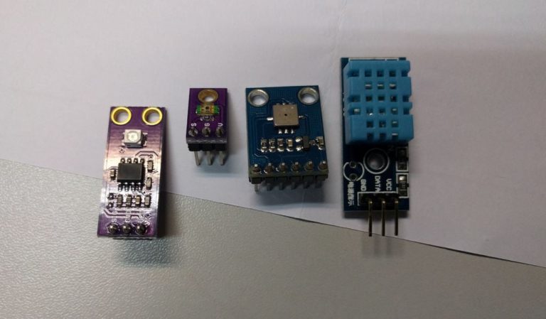
You can build the circuit with the following sensors or simply buy the module boards of those sensors or module board.
- Ambient Light Sensor TEMT6000 (Datasheet PDF)
- Pressure and Temperature Sensor BMP085 or BMP180 (learning document from Adafruit)
Note: They are old products, you may need to find other alternatives. - Temperature and Humidity Sensor DHT11 (learning document from Adafruit)
- UV Light Sensor GUVA-S12SD (Datasheet PDF)
For the uses of sensors, I have attached some reference links. You may find some useful tutorials and references on the internet.
Step 2: Preparing the Main Processor
I have chosen the Arduino Uno board to test the system and coding. However, I found that Atmega328P has not enough memory to store and run the code if more sensors are added. Thus, I recommend that you can use the Atmega2560 Arduino board when you need more than 4 sensors.
Microcontroller Units (MCU):
- Atmega328P board for Arduino, or
- Atmega2560 board for Arduino
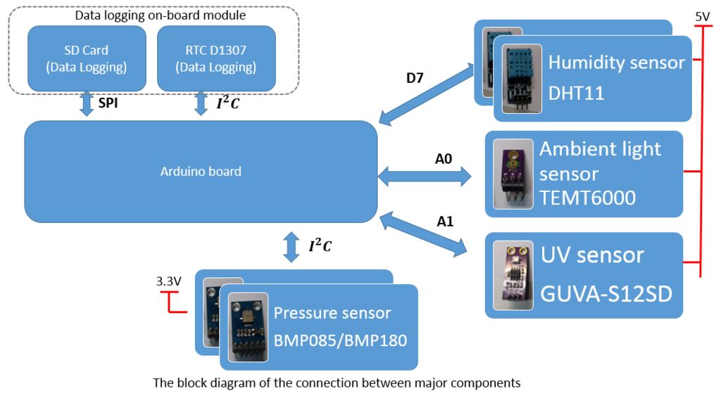
Step 3: Preparing the System
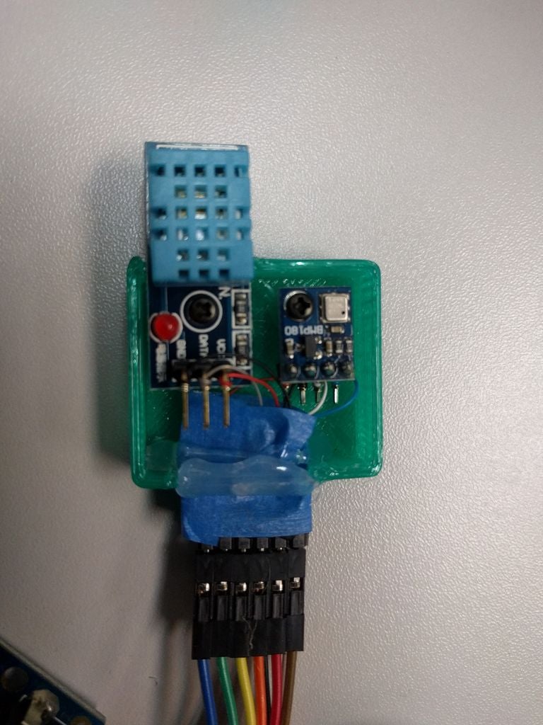
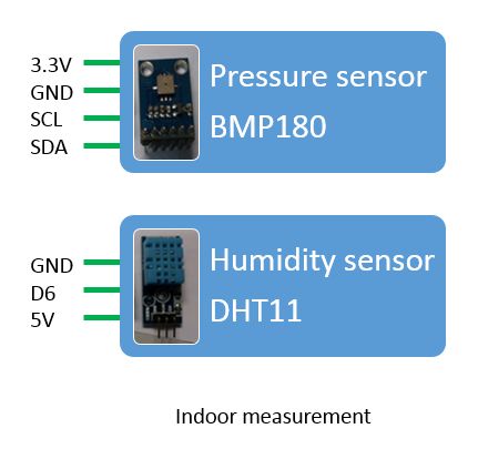
Indoor sensors
These two sensors will measure the room temperature and humidity
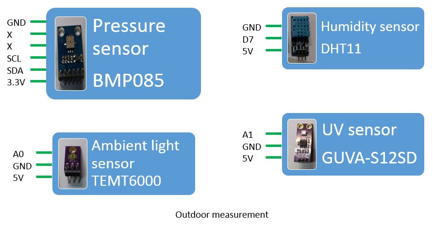
Outdoor sensors
These sensors will measure the outdoor environment
I would like to measure some physical characteristics at outdoor and indoor. Finally, I connected the following sensors to an Atmega2560 board.
For indoor environment:
- Pressure and Temperature Sensor BMP180 × 1 piece
- Temperature and Humidity Sensor DHT11 × 1 piece
For outdoor environment:
- Ambient Light Sensor TEMT6000 × 1 piece
- Pressure and Temperature Sensor BMP085 × 1 piece
- Temperature and Humidity Sensor DHT11 × 1 piece
- UV Light Sensor GUVA-S12SD × 1 piece
You may find that I used different sensors for measuring the pressure. It is just because I don’t have BMP180 module board when I was building the circuit. I recommend that you should use the same sensors if you need to have a precise measurement and a fair comparison.
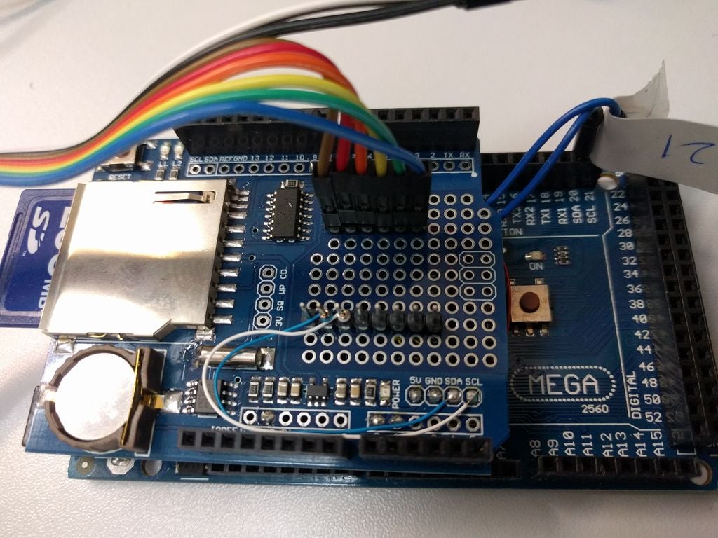
Step 4: Preparing the Data Logging
In addition, I would like the device to store the data without connecting to a computer. I added a data logging module with a real time clock. The followings are the items for data logging and wires connection.
- SD card
- CR1220 coin battery
- Data logging module for Arduino (learning document from Adafruit)
Step 5: Preparing the Tools
The followings are some tools or devices that would be needed to build the circuit.
- 30AWG Wrapping tool
- Soldering iron
- Soldering wire (No lead)
- Breadboard
- 2.54 mm headers
- Jumper wires
- Wrapping wires (30AWG)
- Hot glue
- 3D printing (If you need a case for your device)
- Arduino IDE (We need this to program the Microcontroller board)
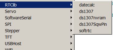
Step 6: Reset the DS1307 Real Time Clock (RTC) on Data Logging Module

I would like to use the data for scientific experiments. Thus, a correct time measurement is important for data analysis. Using the delay() function in programming would induce measurement error in time-shifting. On the contrary, I don’t know how to make a precise real-time measurement on the Arduino platform only. To avoid sampling time error or minimize the measurement error, I would like to take every measurement sample with a time record. Fortunately, the data logging module has a real-time clock (RTC). We can use it to output the time for data sampling.
To use the RTC, I follow the instruction (link) to reset the RTC. I recommend doing this with the Arduino Uno board firstly. It is because you have to modify the circuit when the Atmega2560 board is used (I2C connection is different). After you have set the RTC, you should not remove the CR1220 battery. Meanwhile, please check the condition of the battery before the data logging.
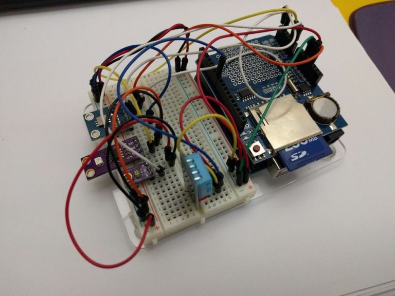
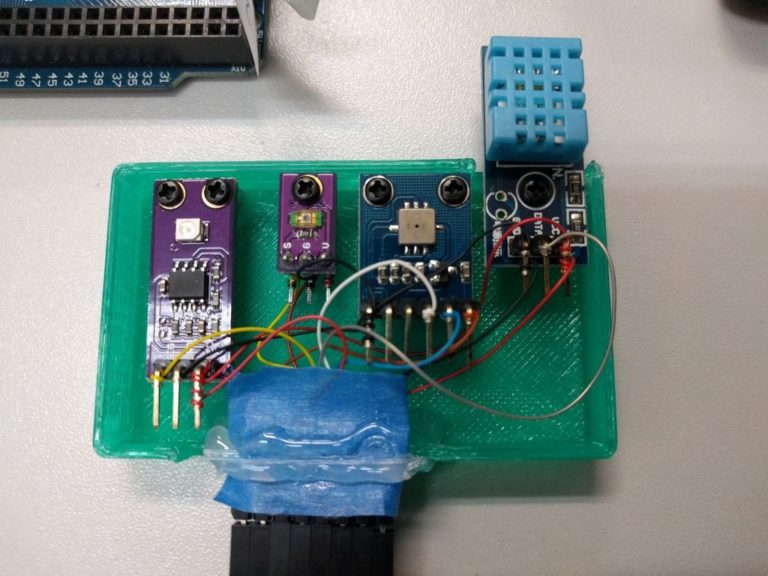
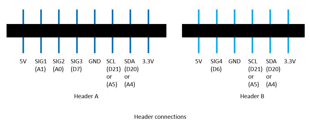
Step 7: Connection
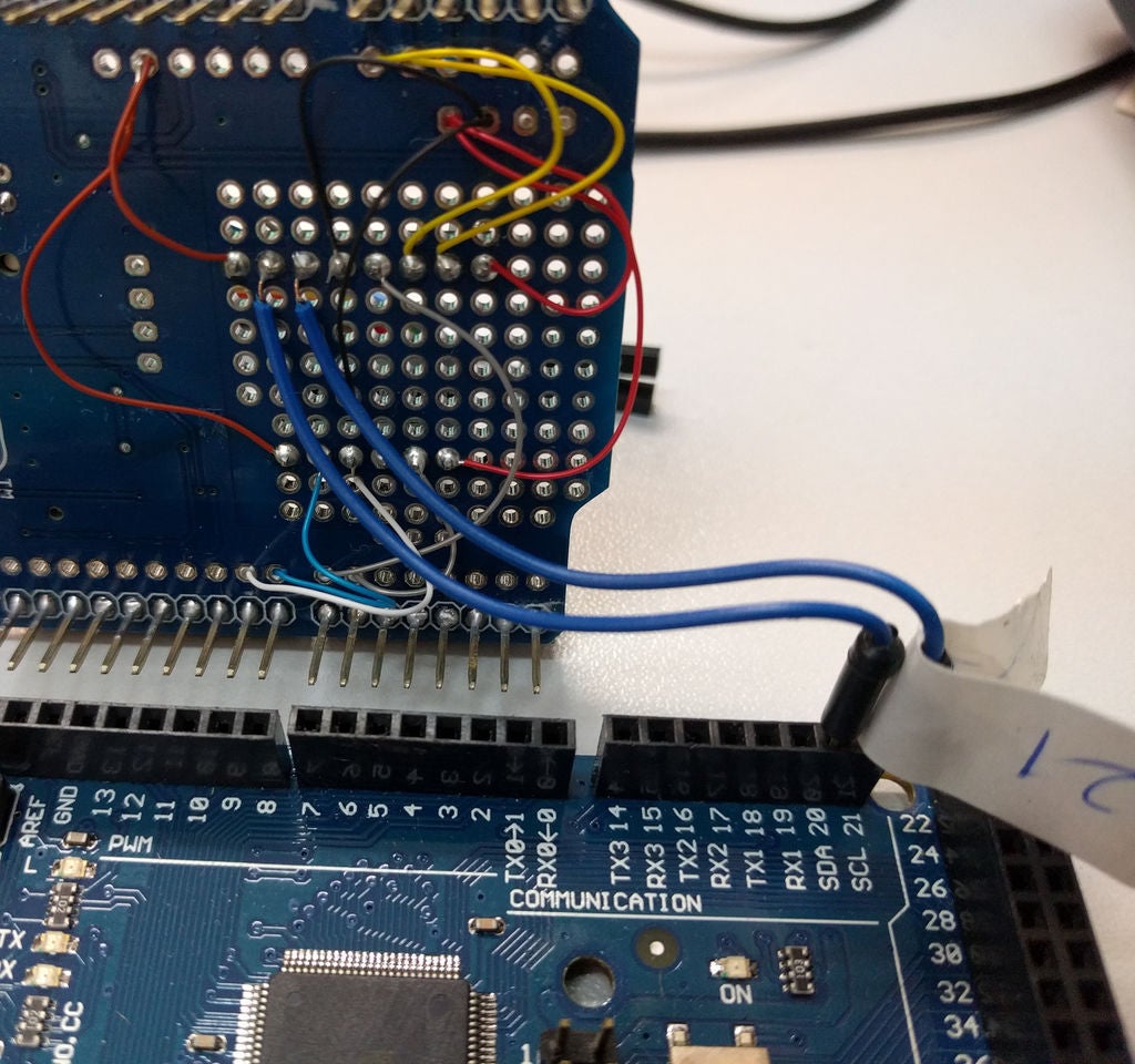
I have separated the indoor and outdoor measurement. Thus, I have made two headers for connecting two different groups of sensors. I used the empty space on the data logging module for mounting the headers. To complete the circuit connection, I use both soldering and wrapping. The process of wrapping is clean and handy, while the soldering joint is strong and secured. You can choose a comfortable method to build the circuit. If you are using the Atmega2560 board, make sure that you have built a jump connection for SDA and SCL pins. The connection of the RTC on the data logging shield must be reconnected.
To connect the sensors, I soldered the headers on the sensor modules, and then I used wire wrapping to link all sensors to the headers. When you are using the sensor modules, I recommended that you should check the operating voltage carefully. Some sensor modules accept both 5V and 3.3V inputs but some are restricted to use either 5V or 3.3V only.
Step 8: Programming the MCU
Fortunately, I can find the application examples for all the sensors. If you are new to use them, you may download them on the internet or you may install them by using the library manager in Arduino IDE.
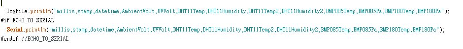
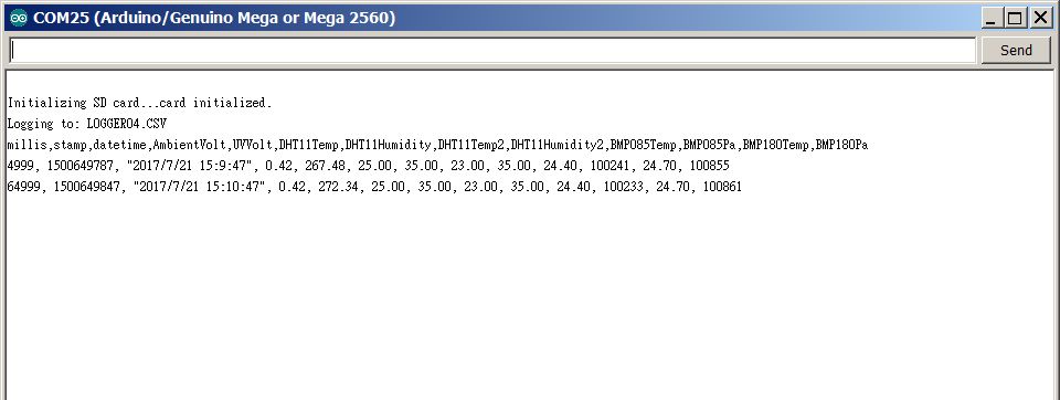
I programmed the system output a string for each sample. The string will be output and stored in the mounted SD card. If you need to view the data, switch off the device and then unmount the SD card. Then, you can mount the SD card to a card reader. The file will be stored as a CSV file. Once you have download the data file to the computer, you can view it by a text program or a worksheet program.
Step 9: Test It and Use It!
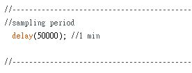
It is important that you do understand the meaning of the data. The sampling frequency is one of the important parameters. The current measurement time interval is 1 min, you may need to change it.
In addition, you would find the temperature measure of DHT11 is not accurate. If you need a more precise value, you can just use the temperature reading of BMP pressure sensors.
Thanks for reading this!
This article was originally published at www.instructables.com on Jul 25th, 2017.
If you enjoy this post, please share it on Facebook and Twitter. You might also support us by making a donation through Ko-fi.