Previously, we have published a demo video about making our logo with CNC 3D engraving. You can do the same if you have a 2.5D CNC engraver or a 3D CNC milling machine. Here is a simple tutorial starting from CNC text engraving with Roland Dr.Engrave.
If you buy a Roland machine, you will get their CAM software and their licenses.
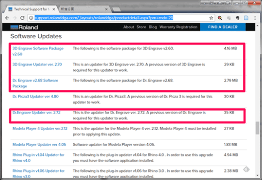
But some old software, including Dr.Engrave and 3D Engrave, is free to download from Roland DGA website. Of course, the software is designed for Roland’s machines but you can change the RML-1 file to a G code file with our free rml2gcode converter. It should be much easier than generate G code in Inkscape.
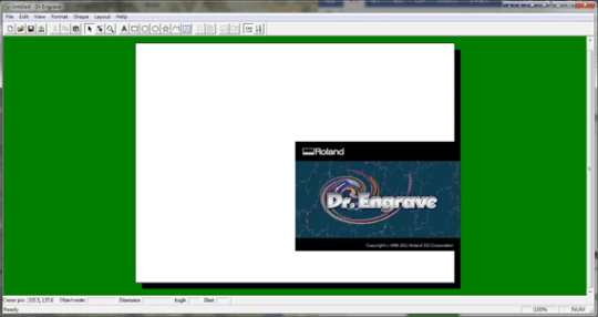
Downloading the install and update files, you can then install Dr.Engrave on your Windows PC. Launched it, you will see the layout below. The software works in 2D because that is enough for CNC engraving texts and patterns with a fixed depth of cut. It is not necessary to design in any 3D CAD software, that saving costs and efforts. So, you can put more money and power into testing different materials.
Creating a Text Tool Path
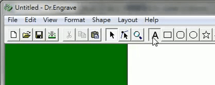
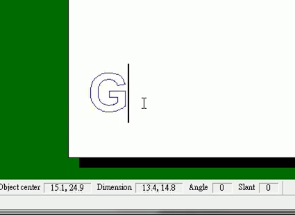
First, use Draw Text to create a text object. You can find the tool in the toolbar as shown below. Then, type a text to the canvas as you like.
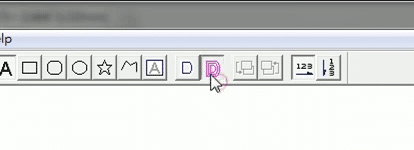
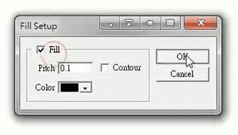
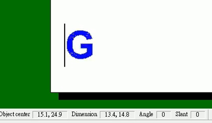
Second, use Fill to generate an engraving tool path. The material inside the text contour will be removed. The blue lines represent the generated tool path.
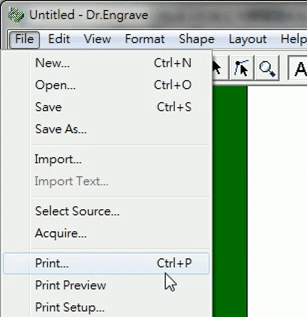
Third, use Print… (Ctrl+P) to export the design to be a Printer job.
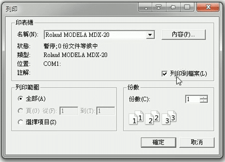
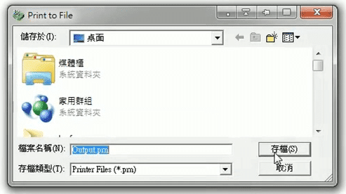
To preview the machining results, click “Print as a file” in the print dialogue.
Verify the tool path
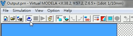
Now open Roland MODELA to simulate the cutting results.
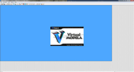
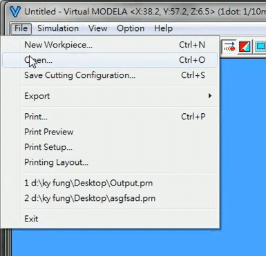
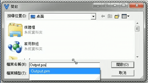
First, use File > Open (Ctrl+O) to load the previous tool path file to the program.
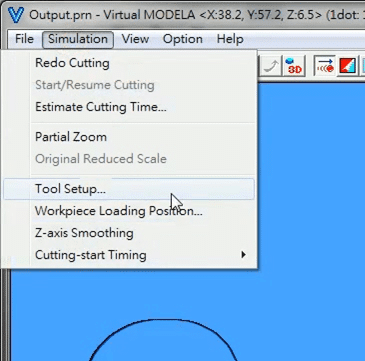
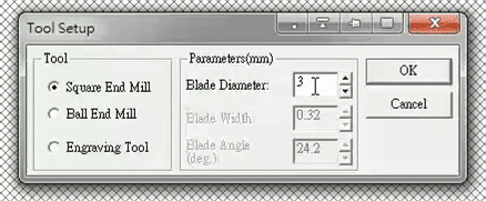
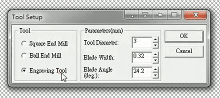
Second, go to Simulation > Tool Setup… to define your cutting tool. For example, we choose a square end mill as the tool and 3 mm as the blade diameter.
Press Redo Cutting, it will simulate the results with the corresponding parameters.

Third, you can obtain different results with the same tool path by changing the tool setup. For example, we choose (V-shaped) engraving tool this time. You can input the tip size and the blade angle according to the specification of your cutters.

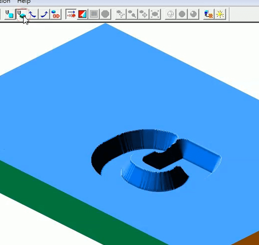
Bevel edges are obtained this time. You can switch to 3D simulation to better verify the 3D results.
If you have any issues about the machine, you can visit our page FAQ for Roland Modela MDX-20 to find more solutions or leave your questions in the comment section of the FAQ page.
If you enjoy this post, please share it on Facebook and Twitter. You might also support us by making a donation through Ko-fi.